Wednesday 19 February 2014

Designing for the Internet of Things

Real good read about products the internet and where it is going - NPD...
SolidWorks Internet of ThingsIn the first part of our series on designing for the Internet of Things, we mentioned that it’s estimated that by the year 2020, somewhere between 50 and 100 billion devices will be connected to the “Internet of Things”—the phrase used to collectively describe all of the non-computer devices actively linked to the Internet.
In order to maximize this potential, we need to take it upon ourselves to ease the introduction of these devices into the digital infrastructure. For a designer, the most important way to ensure that you are doing your part is to constantly remind yourself who you are designing for: the Individual, the Business, or the System (government agencies). Today we focus on designing for the Individual.
While the Internet might have been developed as a government network, it is really the Individual who made it a versatile tool for work and play. When you are designing an Internet-based device for the Individual, it is imperative to capitalize on his or her creativity:
  • Create objects that are compatible with a broad range of lifestyles and technical aptitudes.
  • Don’t add features that you think some people might use, or might learn to use in time.
  • If you’re torn because you want to add a feature that you know is complicated, leave it on the back burner for a future iteration, optional downloadable content, or a future “deluxe” model.
Current IOT Tech
Any first release model needs to be basic so that the Individual can master it quickly and know that he or she is in complete control. Few people want or need 100 percent control of any given device, but they do want the ability to change proprietary settings and close unnecessary programs. The Individual is more comfortable with technology when he or she  knows what a device is doing and has control over it. To this end,
  • design devices that offer a clean slate of content so that the Individual can be creative and make it his or her own;
  • start simple and give the user the ability to customize a device in a way that conforms to his or her unique lifestyle;
  • do not overwhelm the user with a list of things that you think are good for him or her.
Your device will be more successful if it has fewer features than if it has too many, because the Individual will know what he or she is getting and what he or she will need to learn at the time of purchase. Remember, it is not the Individual’s job to learn how to use a device, and he or she will stop using it (or refrain from buying it altogether) if he or she thinks the learning curve is too steep. To help make your device a success, consider these factors:
  • Design logical devices that are easy to operate and demonstrate very obvious potential for reward.
  • The Individual must see the device as an upgrade over something already owned, or improvement to his or her quality of life without adding any hassle. The value add must be real and marketable.
  • The device must be compatible with the most disparate set of networked devices possible.
  • If the device is too proprietary and doesn’t work well with others in an ecosystem, it’s likely to gain a bad reputation quickly
In our next installment, we’ll discuss the approaches design teams should consider when developing connected devices for the Business.
In the meantime, visit our website to download our new feature article: Designing for the Internet of Things, as well as sign up for a February 25 webinar on the topic.You can also download our new infographic on The Internet of Things–Past, Present and Future.
Internet of Things Blog Infographic

Tuesday 11 February 2014

3D Printed Surfboards

New surfboard fin riding wave of 3D printing

Feb.5, 2014

In Putaruru, New Zealand, well-known surfboard maker Roy Stuart is among the first in the world to incorporate 3D printing technology into his surfboard designs. He took inspiration from the Humpback whale in creating the design for his hollow, Warp Drive BLEF foiled surfboard fin which was 3D printed with the help of specialists at Palmer Design and Manufacturing based in Tauranga, New Zealand.

Stuart holding a BLEF foiled fin

Stuart looked closely at the pectoral fins of Humpback whales in creating his surfboard fin design. The fin features a hollow core and surface tubercles – or BLEF (bumpy leading edge foil) – which mimic the skin of Humpbacks.

Normally, Stuart's handcrafted surfboard fins can take over 40 hours to make. Fiberglass fins can be especially troublesome as they are expensive, tricky to mold, and difficult to adhere to the surfboard.

This is where the wave of 3D printing ebbs into the story.

Late last year, Stuart brought his fin design to the 3D printing specialists at Palmer Design and Manufacturing. In a matter of a couple of months, they helped Stuart create a 3D CAD design for his surfboard fin and 3D print the fin using ABS filament and, finally, a polycarbonate material. The fin was put through rigorous strength tests like the one seen in this video.

Stuart is well-known as an innovator in wooden surfboard designs and is please to add 3D printing to his repertoire. He sees 3D printing as another way of bringing new designs to life and embraces the possibilities 3D printing offers for his work. "We can more of less do anything we want now," says Stuart.

Fins are 3D printed in vibrant, translucent colors ranging in size from 6.5 to 9 inches and in price from $82-$164. The fins are suitable for any boards with a standard fin box.


For an incredibly leisurely look at the 3D printed Warp Drive BLEF foiled surfboard fin in action, check out this video:

Posted in 3D Printing Applications


Colin Rose (M Eng) | Design Engineer | Future Products Group
www.fpgworld.com
p: +64 6 843 3249 f: +64 6 843 2466
Asia: 0086
21 3351 3390 | Au: 1800 041 649 | NZ: 0800 367 374 | UK: 0808 234 7922


The Man Who Prints Houses

The Man Who Prints Houses - Documentary about Enrico Dini and his heart and soul in 3D printing buildings

Feb.16, 2012

"The Man Who Prints Houses" is a upcoming film about a genius in the 3d printing world who intents on changing the world forever.

Enrico Dini is the man who prints houses. He is an Italian inventor who has developed a new construction technique based on the principle of 3D printing. His largest 3D printer in the world - can build 3D objects from sand and a binding agent.

The film follows Enrico from his ambitious business ideas, to financial problems and struggles in his family life. It shows some of his innovative projects: constructing the tallest printed sculpture in existence, working with Foster + Partners and the European Space Agency on a programme to colonise the moon, solidifying a sand dune in the desert, and printing the closest thing to an actual house: a small Italian dwelling known as a trullo.

Enrico Dini's D-shape 3D printer is a large aluminium gantry structure, which uses CAM software to drive a huge print head during the building process. It can print buildings - at least the most parts of it - on site with much less manpower needed for construction. It deposits sand followed by an inorganic binding material. Excess material acts as a support to the binded structure and when the print is finished the excess material can be removed and reused. This process has low maintenance costs and no water is used since the component parts are 'mixed' when they meet outside of the inkjet nozzles.

Enrico dreamt of building objects with impossible shapes. With his D-Shape 3D printer they could make previous impossible forms. His largest structure "the Radiolaria", is a 2m tall sculpture inspired by the architect Andrea Morgante. It took him ten days to print the structure. A full scale of 8.5m high version of the Radiolaria has been installed in Pontedera Italy.

Watch trailer of The Man Who Prints Houses after the jump.

image credit: Enrico Dini

Source: boingboing& develop3d


Colin Rose (M Eng) | Design Engineer | Future Products Group
www.fpgworld.com
p: +64 6 843 3249 f: +64 6 843 2466
Asia: 0086
21 3351 3390 | Au: 1800 041 649 | NZ: 0800 367 374 | UK: 0808 234 7922


Thursday 6 February 2014

Can a bicycle be ridden at 112mph?


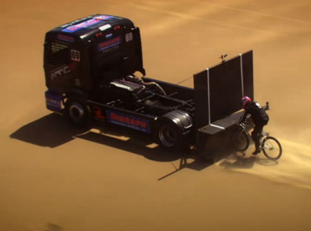
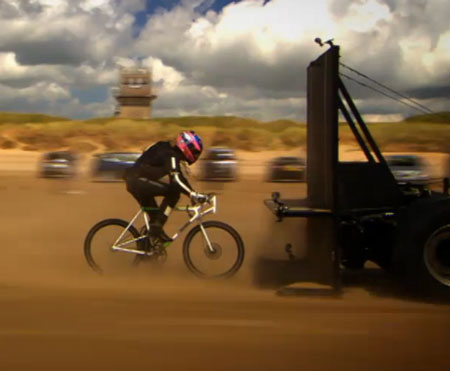
On August 13th 2013 Guy Martin reached 112.94mph on bicycle cycling behind a modified racing truck at Pendine Sands, South Wales and became Britain’s fastest cyclist. For the preceding eight months Guy Martin had been working with Dr. Jason Hill of Dynamiq Engineering Ltd (a Solid Solutions customer) to develop the aerodynamic and structural modifications for the racing truck necessary to make this record breaking speed possible.
Heli Image Pendine Sands - Solid Solutions Customer
Dynamiq Engineering Ltd, were tasked by the production company to develop a suite of modifications to Dave Jenkin’s racing truck to create the largest possible slipstream, hence eliminating the aerodynamic drag that Guy would have to overcome and allowing him the reach the record breaking speed of 112.94mph. The modifications involved the design, simulation and testing of a screen canopy to create the strongest possible aerodynamic recirculation behind the truck. The objective of the aerodynamic design was not only to eliminate drag, but if possible to create a positive thrust on Guy to help overcome rolling resistance.
Numerous canopy designs were considered, including partial and full enclosures, deflectors and simple screens. 3D CAD models of the truck and the canopies was developed in Solidworks and extensive engineering simulation carried out. Initially the simulation focused on flow analysis to optimise the strength and scale of the wake generated by the truck. Transient flow simulations were carried out to capture the motion of the wake and help Guy visual the violently unsteady, chaotic and turbulent environment in which he was hoping to cycle at over 110mph.
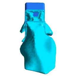
It can be observed that the CFD gave good qualitative agreement between the wake shape and scale between the CFD flow visualisation and the images filmed by the aerial film crew capturing the record attempt for a TV series.
CFD Iso Surface Plot - TheoryCFD Iso Surface Plot - Practice
Theory & Practise:  CFD Simulations compared with the particle traces obtained by the sand becoming entrained in the wake of the vehicle.
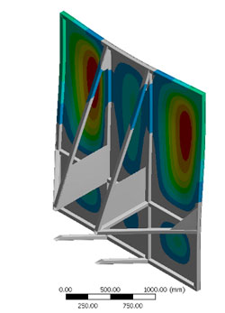
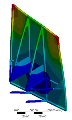
Once the technical decision had been taken to adopt a simple screen canopy and the performance calculations had shown that the racing truck would have sufficient power to be able to attain record-breaking speed with the additional aerodynamic drag, then the mechanical design and simulation was undertaken.  It was vital that the structure supporting the screen could handle the structural loads and avoid any potential vibration arising from such unsteady aerodynamic excitation.
Again a detailed 3D model of the underlying structure was developed in Solidworks and a detailed static structural and vibration analysis undertaken.
SolidWorks Static Structural AnalysisSolidWorks Modal Analysis
(i) Static Structural Analysis(ii) Modal Analysis
 The design was found to be strong and stiff enough to meet all of the required safety criteria and therefore fabrication of the prototype canopy was undertaken by the team at Jenkin’s Motorsport.
Once complete the canopy was subjected to a one-day test program from both an aerodynamic and structural perspective at a dis-used aerodrome in Staffordshire, UK.  Initially, the canopy was attached to the truck a series of runs made at progressively higher speeds along the two-mile run-way with structural inspections being carried out in between each run.
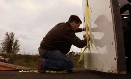
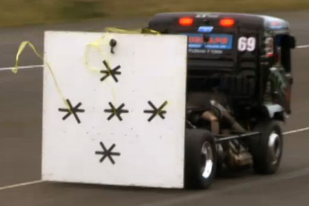
Once it had been determined that the canopy structure was adequate, ribbons were attached to the rear of the screen the help visualised the flow field behind the truck.  The CFD suggested that the flow on the face of the canopy would be directed forward in the direction of travel and then outwards along the board, therefore if the aerodynamics were working as planned the ribbons should have been extensive pinned to the back of the canopy.
Attaching-Testing-Ribons
Testing-Ribons-In-Action
Testing:  Ribbons were attached to the rear of the screen to help visualise the flow behind the screen.  At all speeds above 40mph the ribbons were seen to be pinned to the back of the canopy exactly as-designed and simulated.
With all of the testing complete and the truck working as designed the date for the record attempt was set for August 13th 2013 at Pendine Sands in South Wales, UK.
Originally it had been planned to attempt the record at a UK-based proving ground on an oval concrete track, but at the last minute this had to be abandoned due to safety concerns.  The only other location deemed suitable was Pendine Sands.  A hard tidal sand beach used as a weapons testing range and owned by the UK ministry of defence.  The beach was far from ideal from the point of view of the record attempt.  The higher rolling resistance and lower traction of the surface made attaining the record speed far more difficult and the stability of both vehicles was also substantially reduced.  Furthermore, as the beach dried out during the day, loose sand was entrained into the recirculating wake of the truck reducing visibility behind the canopy at times to around 1m.
However, despite all of these factors just after lunch Guy Martin rode his bespoke bicycle millimetres from the back of the truck and attained a maximum speed of 112.94mph, becoming Britain’s fastest ever cyclist.
Side View of Bike
When the telemetry data was analysed after the record breaking run, it showed that Guy had ridden his bike at over 100mph for well over a mile, in near zero visibility, on an extremely unstable surface, less than 500mm away from a 5 tonne racing truck.
Top View of Bike
This record attempts forms part of a 4-program series currently being shown in the UK on Channel 4, in which Guy Martin attempts to break four speed related records including, outright speed on a bicycle, hydroplaning a motorcycle, fastest human powered flight and downhill sledging.  These series can be viewed online at:  http://www.channel4.com/programmes/speed-with-guy-martin
While there is no doubt that the success of this record on the day was due to Guy’s skill and experience in handling the bike under incredibly difficult circumstances, the record itself was made possible and all of the risks minimised through the extensive use of 3D CAD, finite element analysis and computational fluid dynamics by engineers with the expertise to use the technology correctly.
- See more at: http://blogs.solidworks.com/tech/2014/01/can-a-bicycle-be-ridden-at-112mph.html#sthash.NNycouy9.dpuf

Monday 3 February 2014

Start stacking with Lego in your browser!


Who doesn’t love Lego? Sure, it can get messy and you can run out of bricks (plus it hurts when you step on a piece), but what if you could build your dream designs from the comfort of your web browser? Well, Google and Lego have thought exactly that and have come up with a new app that lets you build almost anything you can think of straight on the web. It’s called Build With Chrome, and it lets you build up on a map of the world, so you can create classic life-like structures if you wanted to. You can also share your masterpieces via Google+, while it also works on your mobile web browser too – did you just say goodbye to your productivity? Who needs Minecraft now?

http://www.buildwithchrome.com/getchrome