Apr 16, 2014
Teardown of the Makerbot 5th Gen Replicator Smart Extruder
In our previous blog post, we just had a quick overview of the new Replicator and its features. Well, we finally got a 5th Gen Replicator in the office. And that means that we finally got to get into the nitty gritty of the bot.
Continue reading to see a teardown of Makerbot's new "Smart Extruder"! (Prepare for a lot of pictures!)
The front of the Smart Extruder
The rear "business end". Note the two rows of pins — These are our thermocouple, power, and signal connectors
There are a ton of features packed into this extruder! We'll tackle them all, but the ones to note are:
· The four circular bosses on the edges: These contain the magnets to hold the extruder in place.
· The fan duct on the bottom: This helps cool the filament as it comes out of the nozzle
· The nozzle/heat block/heatsink: The basis of any good extruder!
· The circular metal inset, left of the connection pins: This is our hobbed wheel. We'll see this in more detail later.
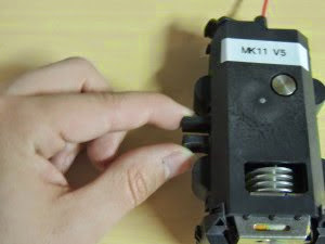
We've been told that filament won't get jammed in this extruder and, while we are hopeful, we are also realistic. We're happy that MakerBot included access to the idler bearing tension arm. This allows the user to release pressure on the filament, and pull it out.
Just grab…
…And pinch!
That's about all we can do from the outside… so let's tear this thing apart!
Like many of MakerBot's injection molded parts, this thing is held together with snap-fit clips. You need to remove both the cooling fan duct and the filament guide before you can split the extruder down its middle.
These clips hold the plastic together.
Some gentle nudging with a flat head screwdriver, and we had popped off the fan duct!
The nozzle in all its naked glory.
Here we get a better view of the heater block. We've still got a cartridge heater, a thermocouple, and Kapton insulation. No surprises there.
One thing that did surprise us, however, was how wobbly the assembly seemed to be! The nozzle and heater block could move up and down by nearly 5mm!
Here's a .gif showing that (Please note that this was recorded slightly out of order… The front cover of the extruder is removed to better show the moving action):
Weird… The only way to find answers was to dig deeper!
The filament guide came off with a gently pry.
The freed guide.
And the bare top.
It's worth taking a break here to discuss the cylindrical tube on the right. According to a source from MakerBot, that was supposed to be the original path for the filament. They found that the sharp turn required inside the extruder would often snap the filament. We don't suggest putting anything through there!
Now that the fan duct and filament guide are removed, let's work on the tabs on the main body.
After some prying with a flathead, we ended up with a freed housing! (And one broken tab…)
Our sandwich, opened up.
The bottom half of the extrudder is dominated by the hot end.
The middle is a pretty classic extruder design — Idler bear on a spring against a hobbed wheel. There's a bit more to it than that, which we'll see later.
And the top is where the "Smart Extruder" gets its name.
The bearings on the hobbed wheel — The ID of which is 10mm
Wow! Look at those teeth!
We pulled out the wheel… Pretty fancy bit of aluminum!
This ends has features that key into the motor shaft on the X-Carriage.
The hot end and idler bearing are tied pretty closely to the circuit board inside…
…Fortunately there's some built in strain relief, so we don't have to worry about breaking the connection.
We're going to take another break here to discuss a major feature of the hot end. When doing fast travels, the nozzle (and the rest of the hot end assembly) jump up. This reduces stringing between towers, and also lessens the chance of knocking over a tall print.
Remember earlier when we said our assembly was "wobbly"? Turns out, that's a feature, not a bug!
So how does this work? Some people have been speculating that it's a solenoid action, but it's even simpler than that (At least, on the Smart Extruder side).
Here I'm using red filament to point out a hard to see feature… A small (but VERY powerful) magnet.
**We've had some great insights down in the comments: There's speculation that this magnet is used with a Hall Effect sensor to determine the Z-Position of the nozzle.**
We haven't figured out how to safely open up our X-Carriage yet, but we hope to do so soon!
Anyways, on with the show.
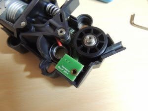
There's a small, upside down circuit board at the top of the Smart Extruder. The text says "Yonkers Rev.F 2014″
…And a what appears to be a mild-mannered idler wheel on the other side.
I first removed the plastic guide in between these parts… I later found that this was a mistake. The circuit board should be removed before the guide. No harm done, thankfully.
Now let's look at that board…
The reverse of the board!
But what's that little triangle on top?
A tiny switch! This appears to be how MakerBot checks for filament in the extruder.
The 4-pin connector on the tiny board connects to the main Smart Extruder Board here.
A 2mm hex wrench gets that mild-mannered idler wheel loose…
…But surprise! Turns out there's more to this than we thought!
That filament is pointing at what looks like a tiny sensor, oriented just underneath our encoded idler wheel!
So it appears that the Smart Extruder is actually… well, smart! And MakerBot seems to have covered the two main modes of failure due to filament:
· A microswitch ensures that filament is being fed into the extruder. No more running out mid print!
· An optical rotary encoder ensures that your filament is actually feeding. If the bot thinks that it's pushing plastic, but the wheel isn't spinning, then the filament has gotten stuck for some reason.
We haven't had a chance to really stress test the smarts on our extruder, but it looks promising!
Here's the best view of the main board that we could get. Loosen a couple of screws and…
…We can see the other side! Nothing too interesting, other than the filament sensors and the fancy quick-connect pins. The text at the bottom reads "MakerBot Industries Yonkers Rev.F 2014″
And that's it! Reassembly was relatively simple, except for aligning the hot end. It took a few tries of disassembling and reassembling before the hot end assembly would reliably perform its retraction.
Overall, it is clear that MakerBot is moving farther and farther away from the "tinkering" mindset, and more towards the "Plug-and-Play" mindset. They started with Cupcake and Thing-O-Matic kits, moved to pre-assembled wooden Replicators, then to the steel (but still hack-able) Replicator 2s, and have ended up with the 5th Gen Replicator — A machine that is meant to work largely as a black box (In addition to being, quite literally, a black box).
This is both good and bad — inexperienced users will be able to fix their machine with a very simple swap outs, but users that are comfortable with implementing their own fixes are now challenged even more. We really hope to see improvements to the Smart Extruder on Thingiverse, like we did with the original Replicator's extruder block, but we're guessing that the number of people who actually implement those hacks will be few and far between.


